

Automated Test System uses PXI to Validate Irrigation Control Panels
- markvasat
- Nov 21, 2022
- 3 min read
Updated: Oct 19, 2023


Left. Irrigation control panel test enclosure. Right. Two DUTs are being loaded into the test enclosure.
The Challenge
A designer and manufacturer of irrigation systems approached us with the need for a system to test and validate the control panel and outdoor sensor of their residential sprinklers.
The Solution
Using hardware and software to create a full turnkey solution for automated testing, we were able to help improve the client’s quality control process and the efficiency of their final product testing.
The Story//The Cyth Process
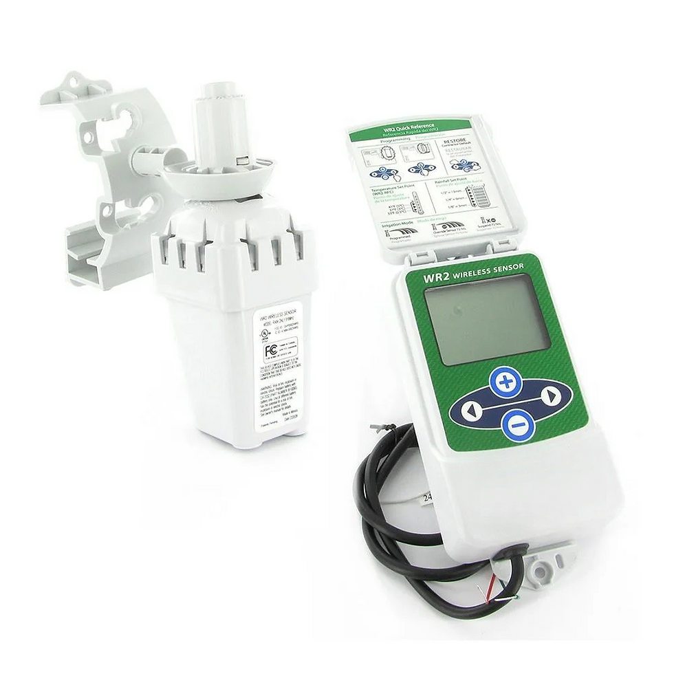
A global provider of irrigation products approached us with the need for a system to perform validation testing of their residential sprinkler system control panel and outdoor sensor. Their product was a two-part system that worked in tandem to automate the control of one’s sprinkler system. The outdoor sensor was designed to measure rainfall and temperate and relay this information to an indoor control panel. The indoor control panel then decided from the transmitted information and the scheduled presets the customer chose whether to irrigate one’s landscape. The two communicated using radio frequencies (RF) which increased the product’s ease of use, as the outdoor sensor was mounted on one’s roof and communicated wirelessly with the control panel located in the interior of one’s home.
The product testing of the outdoor sensor and indoor control panel required testing the functionality of the two-part system. Our engineering team recognized this required testing the control panel’s physical buttons, the device’s interior software, the segmented LCD screen, and the RF signal transmitter (outdoor sensor) and RF signal receiver (indoor control panel).


Figure 3. The NI PXI chassis and I/O cards contained in the test enclosure.
Our engineering team began by building a test fixture centered around a PXI hardware chassis, several I/O cards, and NI TestStand software that controlled and monitored all aspects of the device testing. The wide range of the PXI designated card slots provided the ability to acquire the wide range of high-speed I/O required. NI TestStand provided our team with the ability to program and automate the procedural sequence of the fixture’s testing.
Control Panel Feature | Test Method |
Button Membrane Switches | NI PXI 4110, Mechanical Plungers |
Device Power Consumption | NI PXI – 6514, Industrial Digital I/O Card with DBL Voltage Cable |
Segmented LCD Screen | Camera with Ethernet Comm |
RF Signal Analyzer | NI PXI 5661, VSA – Vector Signal Analyzer (inbound signal) using Digital Signal Attenuator |
RF Signal Generator | NI PXI 5661, VSG – Vector Signal Generator |
Test Fixture Procedure
Indoor Control Panel
The automated test enclosure is opened by the operator.
Two units are slotted into the provided nests.
The operator wires the units to the fixture, and the enclosure's cover is closed.
The system automatically powers up the units, measures current, and validates RF data from the RF signal analyzer.
The system then presses the button membranes 1 – 4 of the control panel and uses a camera to inspect the relayed output of each button on the LCD screen.
All the test data is read by TestStand and the PXI hardware and stored to the PC's memory.
The operator opens the enclosure cover, removes the tested units, and repeats.
Outdoor Sensor
The automated enclosure is opened by the operator.
Two units are slotted into the provided nests.
The operator wires the units to the fixture, and the enclosure cover is closed.
The system automatically powers up the units, measures current, and validates RF data from the RF signal generator.
The system downloads firmware to the outdoor rainfall sensor and validates the temperature data to the measured value.
All the test data is read by TestStand and the PXI hardware and stored to the PC's memory.
The operator opens the enclosure cover, removes the tested units, and repeats.


Figure 4. Two irrigation control panel DUTs are electronically wired and awaiting test.
Delivering the Outcome
Overall, our engineering team was able to deliver a full turnkey solution for the automated testing of our client’s sprinkler system. Both the outdoor sensor and indoor control panel were tested using the same automated test fixture. This was achieved through our engineering team integrating NI TestStand software, NI PXI hardware, and an industrial PC control system to be able to execute defined testing sequences and monitor the responses in real-time. The flexible I/O modules enabled us to control several different devices from mechanical plungers to an ethernet camera to test the various features of the sprinkler system (buttons, software, a segmented LCD screen, and the RF signal analyzer). We were able to provide the client with a system that accelerated their quality control process through the in-depth testing of 300+ units a day. The operational bulletproofing of the test fixture has ensured the product validation and optimal function of our client’s sprinkler system in preparation for their use across homes nationwide.

Technical Specifications
1 x Optical Sensor – Photodetector
1 x Cable USB - Serial TTL Converter
1 x Ethernet Camera
Plungers
1 x Airflow Control Valve w/ Exhaust Muffler
1 x Solenoid Control Valve
1 x Compact Extruded Aluminum Air Cylinder
1 x Magnetically Actuated Switch


Comments